I recently found myself wanting to be able to code up some animations and maybe some graphs for my youtube channel (Zanzas Toys), but wasn’t able to find a good tool for creating 2d animations with code and outputting video. So, I decided to make one, and Veve was born.
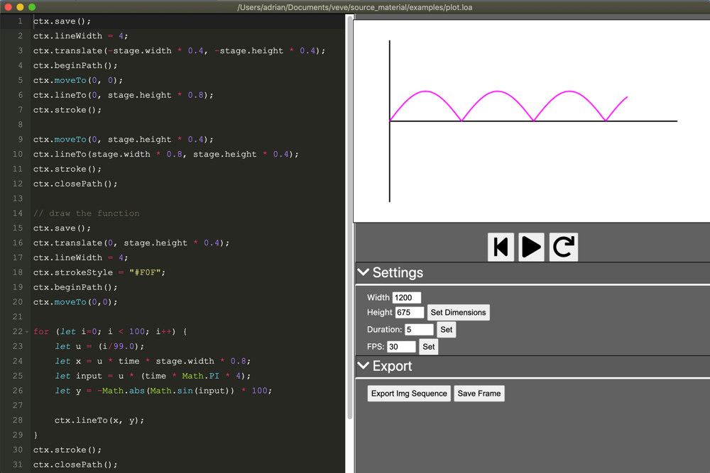
I really like using the canvas API for drawing 2d content, and I’m really comfortable with it, so I made an Electron app that allows the user to write code (in the left half) that is then used to draw content into a canvas (on the right). For the text editor, I used Monaco, which worked out really well.
The user can set the dimensions of the canvas, the duration, and the FPS, control the playback with buttons underneath the canvas, and export the result as a single image, an image sequence, or a video.
It also saves the user code and document settings to a custom file format (basically just json) named “.loa”.
Here’s a short video of what it looks like to code up a simple animation using it:
I’ll eventually open-source it, but it needs a little more work before it’s ready for that.
Lots more progress on my web-based parametric modeler for 3d-printable tech panels. I’ve added in two new feature types:
handles: similar to the kind of handles one sees on rack-mounted equipment, including configurable thickness and height from the surface
dials: the kind of indicator you might see on old equipment to provide voltage or other data
I’ve also added in the first steps towards a nicer UI in the right-hand side of the page, including swapping out the parameters based on the selected feature type.
Demonstration of multiple holes being added to a single quad
I’m continuing to work on my web-based parametric modeler for 3d-printable tech panels, and I finally solved what will likely be the hardest problem in the whole (pun not intended) project- supporting multiple holes.
At the start, the system creates six quads that can each receive mouse events. When the user holds space and click-drags to specify a new feature’s location, a couple of things happen, namely:
A new hole is added to the existing quad
The existing quad re-generates its faces to fill in everywhere except the hole (or holes)
The new feature is created, with the hole’s points as its basis
The second step above was the doozy. If there’s only a single hole in a quad, it’s very easy to fill in the necessary faces. This is especially true since I’m making sure that quads are always represented with their points in clockwise order starting at the top left.
However, if there are multiple holes, it gets tricky. One solution would be to throw all the points into a collection and create a Deluany triangulation, but I thought I could leverage the constraints built into my system to my advantage and do something a bit simpler.
Ultimately I ended up writing my own algorithm that sweeps across from left to right, adding the vertical edges of the holes one at a time and creating triangles as needed.
The approach is to:
create two vertical edges for each hole
sort all of the edges by X-coord
init a sweep line with the bottom-left and top-left points of the parent quad
for each edge starting with the left-most:
start with the bottom vert
find either the two or three (see below) vertices in the sweep line that are directly above and below the new vert, and connect them to the vert that’s currently being inserted
insert the new vert into the sweep line at the appropriate position
after each edge is inserted, run along the vertices of the sweep line and check for any concavities. If any three vertices form a concave curve, connect the first and last with a triangle to make it convex
once all of that is done, finish off the quad by connecting the top-right and bottom-right vertices of the original quad to the remaining vertices of the sweep line
You might have noticed that nothing about the above mentioned removing vertices from the sweep line. You may have also noticed that I mentioned that we get either two or three vertices when comparing a new vertex to the sweep line. One of those provides the answer to the other.
Since everything, both the parent and the holes, are quads, that means that sometimes we’ll have a new vertex that has exactly the same Y-coord as an existing vertex in the sweep line (since we’re inserting the right-hand edge of a hole that already had its left-hand edge inserted). In that case, we get three vertices:
the vertex in the sweep line that’s below the new vert
the vertex in the sweep line that’s equal to the new vert (in Y-pos)
the vertex in the sweep line that’s above the new vert
In such a case, the algorithm connects the new vert to the middle and either the top or the bottom, whichever one *doesn’t result in the three vertices belonging to the same hole (since that would create a face inside the hole). It then removes the middle vert from the sweep line.
I’ve recently started working on a web-based parametric modeler for making 3d-printable panels full of greebles/nurnies using javascript and Three.JS. The general idea is to have a base shape and allow the user to draw rectangular sections that then get filled in with additional details.
Currently, the system supports beveled extrusions and arrays of buttons, but more feature types are on the way. To see it for yourself, head here: http://adrianherbez.net/greebles/03/
I’ve been continuing to work on my 3d-printable roguelike, and in order to do that, I needed a way to generate mazes. OpenSCAD is a bit annoying to work with for general programming, so I instead opted to write the maze generation in javascript and export data into the OpenSCAD file.
The maze generation is based on Jamis Buck’s excellent book, “Mazes for Programmers”. The numbers in the cells are there to indicate the contents of the rooms, which can either be monsters (which deal 1-6 points of damage) or food/potions (which heal 1-6 points of health). I kept it really simple on that front- just using numbers between 11-16 for damage and 21-26 for health regen, since all I needed was an easy way to pass the number and type into the OpenSCAD code.
The end result of the mazegen is a set of integer values representing the exists for each cell (each of the cardinal directions being represented by a unique power of 2 and added together), as well as for the contents. Those arrays are pasted into the OpenSCAD source to actually generate the level
Generated grid on left, example drawing on the right
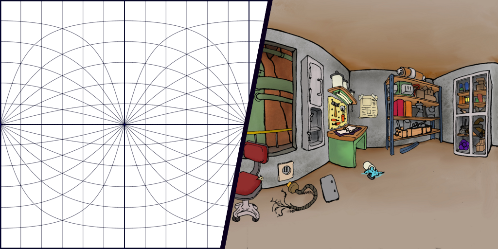
I recently fell into a bit of a rabbit hole with equirectangular projections. They’re a way of mapping the surface of a sphere onto a single image. That can mean unwrapping a ball-like object like the Earth to make a map, but can also be a way to map 360 degrees of an environment to a single image that’s much more readable than say six separate images (as in cube maps).
A side effect of the equirectangular projection being easy to understand is that you can use it to hand-draw virtual spaces. It’s a little tricky to get the hang of though, so having a nice guide definitely helps. To that end, I’ve made a tool using JS that generates an equirectangular grid in a light blue, suitable for printing out and drawing on top of.
See it for yourself here. Right-click on the image to save it, or download one of the PDF versions.
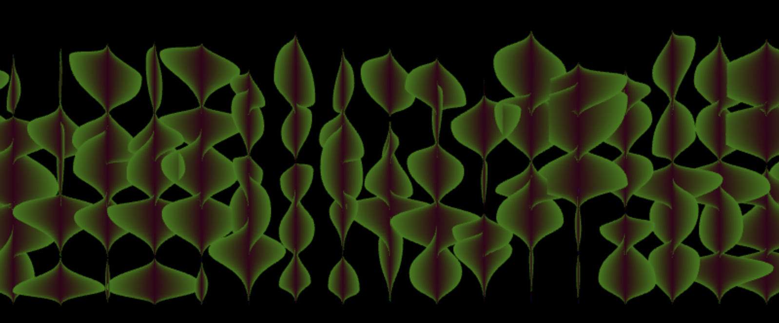
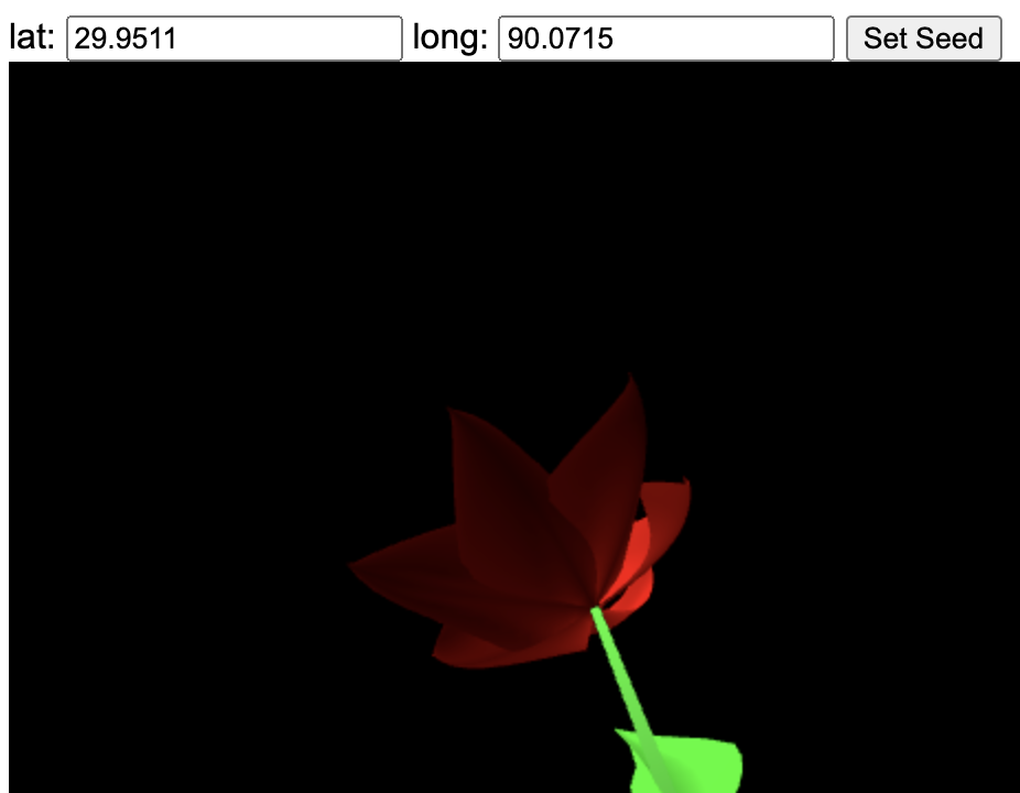
This was a project to create procedural flowers using pure WebGL. All of the geometry and textures are generated via code, and the only external library used is glMatrix. The flowers are also generated using a seed derived from lat-long coordinates, so specific flowers can be generated for specific locations. To see it in action, head here.
Development Process
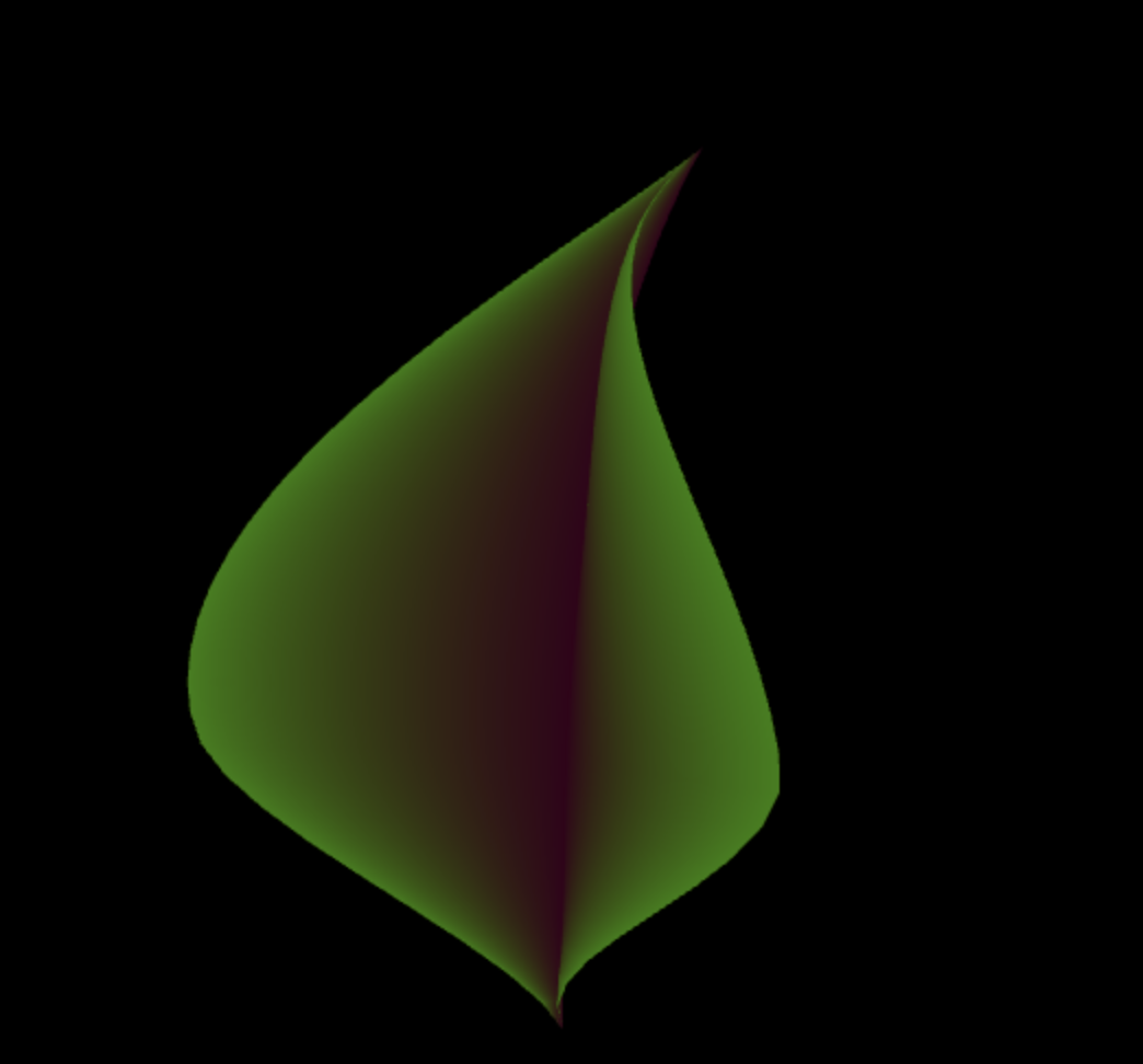
Step 1: Flat leaves The project happened over the course of about a week and a half. I started by generating flat, 2d versions of leaves:
I started by implementing Bezier curves, then using two cubic curves to set the shape of the leaf edge and generating faces to fill in the contents. I also set up a simple shader to have the center of the leaf be a bit red, fading to green at the edges. See this version head here: http://www.adrianherbez.net/glflower/01/.
Step 2: 3d Leaves Once I had the basic 2d leaf working, it was time to add additional cubic curves to make it bend backwards along its length as well as to curve gently away from the spine of the leaf.
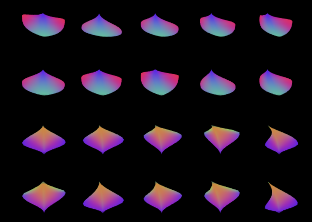
Step 4: Expanding leaves to petals, normals At this point, it was time to move onto the flower itself. I refactored the code for the leaf to be more general, making it a general class for creating geometry from sets of curves (XY, XZ, and YZ). By changing the curves, it was easy to go from pointy leaves to more bell-like petals.
I also added in proper normal calculations for the faces, which also meant writing a normal shader for easy debugging. All of the geometry is rendered double-sided, with one side rendering with the normal color and the other either red (for petals) or green (for leaves). See this version here: http://www.adrianherbez.net/glflower/04/
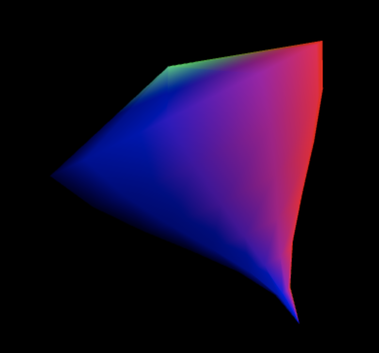
Step 5: Lathed Geometry In order to create the central part of the flower, I created a LathedGeometry class that could take a curve and spin it around the Y axis to generate a sealed piece of geometry.
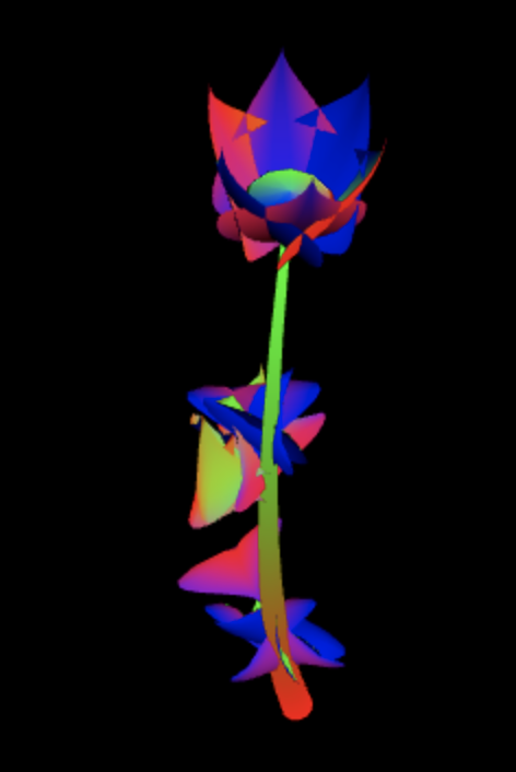
Step 6: Putting it all together Now that I had all of the parts I needed, I put it all together into a full flower, with a stem, leaves, a central element, and petals.
The colors look a bit crazy, but that’s because I was still using the normal shader as a diagnostic. It makes a lot more sense if you see it moving- to do that, head here: http://www.adrianherbez.net/glflower/06/. Moving the mouse in the canvas will change the angle of the flower (added that in to make it easier to see what was going on).
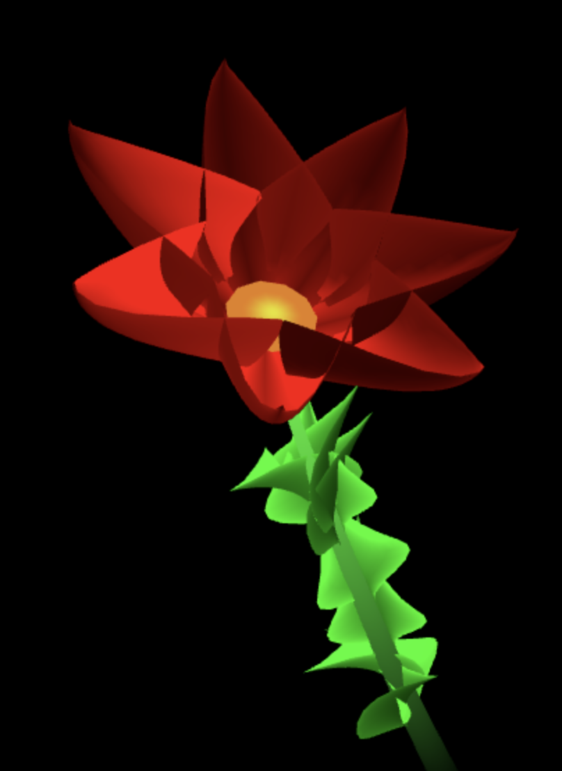
Step 7: Colors! With all of the geometry in, I started working on better colors for the shaders.
Step 8: Lat-long based seed values Now that the flower was close to done, I turned my attention to adding support for a lat/long-derived seed value.
Once set, the same seed is used for all the randomized generation, allowing any place in the world to have its own unique flower. At this point, the colors were still always the same though. See it here: http://www.adrianherbez.net/glflower/08/
Step 9: Finishing Touches I was pretty happy with things at this point, but added a few things here and there to provide some polish, namely: – randomized colors for the petals – modification of the leaf shader to have stripes on the underside – changed the background color to a nice medium gray
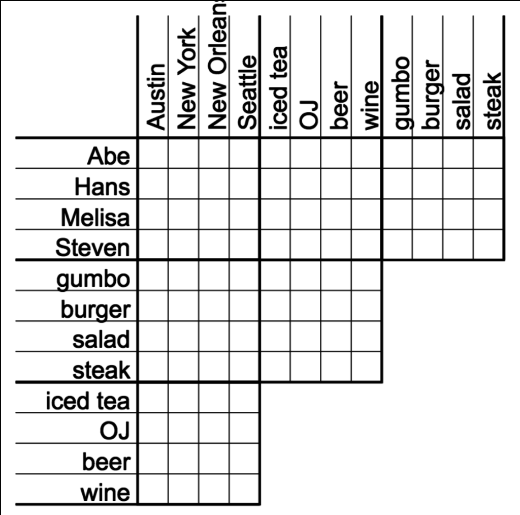
I’ve been a huge fan of logic puzzles since I was a kid, and for a long time I’ve wanted to try my hand at building a system to generate them.
This represents the first pass of such a system- a puzzle is generated, along with 16 clues, pulled from four different types:
Assertion Clues that state that two things are linked (“Alice ordered a burger”)
Negation Clues that state that two things are notlinked (“Alice did not order a burger”)
List All Clues that give one fact for each component of a solution (“The four people were: Alice, the person that ordered the steak, the person that ordered a beer, and the person from New Orleans”)
Either / Or Clues that generate two facts, one true and one false (“Either Alice ordered a burger OR the person from New Orleans ordered a steak”)
I’m pretty happy with what I have so far, though the big missing feature is that there’s no guarantee that a given puzzle is solvable with the clues given. For that, I plan on approaching things by starting with all the possible values, and trimming things away as clues are applied. Once there’s only a single option for each value, then the clues are sufficient.
There’s also a huge amount of room for improvement with respect to the way clue text is generated, so that’s something I want to improve as well. The ultimate goal with this is less about just generating puzzles and more about building logic puzzles into other kinds of games.
To play with it yourself, head here. Note that at present, the generated image is meant to be printed, rather than solved online. That’s mainly because this incarnation is more about puzzle generation (for later inclusion in other projects). Also note that the solution is printed upside-down at the bottom of the page.
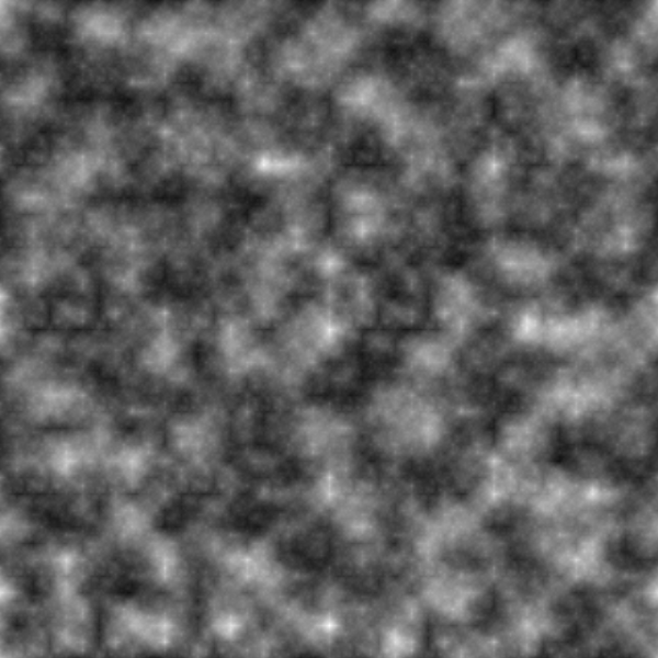
I spent some time recently diving into noise generation, which is something I’ve previously taken for granted. As part of that, I ended up putting together a simple 2d noise generator. The code isn’t particularly optimized or well-structured, as this is just a stepping stone on the way to bigger things. I was pretty happy with the results anyways though, so I’ve put the current state up. See if for yourself here.
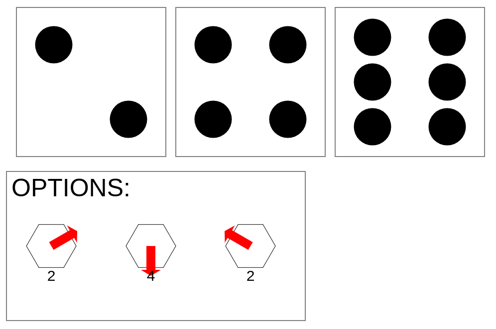
I picked up a few of the books, and absolutely love them. When I gave my girlfriend’s niece her copy, we couldn’t find the required three dice to play. So I whipped up a quick little JS canvas project to roll three D6s. Once I had that working, I went ahead and added some logic to draw the various options available to the player according to the Honeycomb tavern rules.
To use it for yourself, head here. Reload the page to get a new result.

 Follow